OSI Model
At its core, networking simply tackles the problem of how two or more computers communicate with each other. Unfortunately, the field of networking is heavily laden with jargon, loosely used and overlapping terms and I wanted to get to the bottom of it once and for all. Thankfully, the Open Systems Interconnection (OSI) model can be used as a map to explore the field of networking.
Background
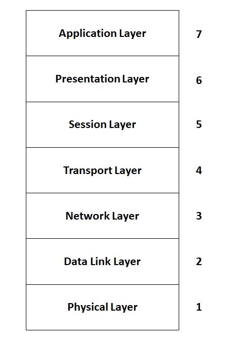
The OSI model abstracts the various objectives needed for reliable communication and breaks these objectives down in layers. The lower layers are the most tangible, as they represent the physical components and the individual bits which make up the data. The higher layers are more concerned with (end-goal) functionality and is how the end users, such as you and me, interface with the network. To highlight the usefulness of the OSI model consider the process of sending data to another computer. It is vital for these two computers to agree on everything from the data structure (i.e. the order of bits) all the way to agreeing on the physical medium used to send data (e.g. copper wire). For complex networks, specifically the internet, in order to transmit this data we will traverse down the OSI model layers introducing more rules and information (typically through headers) dictating how to transmit the data. Conversely, when the recipient receives the data, it will work up from the lowest layer back to the application layer (i.e. the format in which the data was originally sent). By abstracting networking functionality into layers a web programmer is never concerned about the implementation details of the lower layers. They are only concerned with the application layers.
Physical Layer
The lowest layer is the physical layer. This layer refers to the communication medium over which data is sent. To the layman, fiber optics cables or twisted coaxial cables will come to mind. These mediums transmit data over light or electrical signals respectively. What is less apparent is also knowing how we represent these signals physically. For example, a high or low voltage or the sum of two signals can represent a bit (binary digit). A single high/low voltage is simpler to implement but using two signals reduces the possibility of noise corrupting the data. The physical representation of signals is the line coding of the signal and although is not given much thought, it effects how reliable our signal is and how far it is transmitted.
Data Layer
Defines how devices create and terminate connections between each other. The data layer consists of the commonly known IEEE 802 standards for local area (LAN) and personal area networks. These are networks between your own devices only. Naturally, it is useful to have a standard for which different devices, built by different manufacturers for different purposes, to communicate with each other. The IEEE 802 standards provides this standardization for computers connecting in a local area network. The IEEE 802 set of standards is broken up into groups. The popular of these standards is Ethernet defined in the 802.3 group, and wireless LAN (i.e. WiFi) which is defined in the 802.11 group. For interest sake, additional appended characters to the group names define versions of the standards. For example 802.11ac and 802.11ax defines WiFi versions 5 and 6 respectively.
Computers communicating over a LAN will need to agree on a unique way of identifying each other on the network. IEEE 802 defines a Medium Access Control (MAC) number which is a unique number given by the IEEE standards when the device is manufactured. The computers should also agree upon the structure of the data. Data sent over an Ethernet network must be split into data frames (also known as packets) of a set size. These data frames comprise of the source and destination MAC addresses, the data itself and additional redundant data (referred to check redundant cycle [CRC]) that the receiving computer uses to ensure the integrity of the incoming data. The physical device used to connect and transfer data in an Ethernet network is called a switch. Devices connected to an Ethernet network must include a Network Interface Card (NIC), to translate Ethernet frames into useful digital logic.
Finally, it is important to note that at this layer, the medium over which data is sent is does not form part of physical layer. An Ethernet network can send data using twisted coaxial cables or fiber optic cables. So called “Ethernet” cables are more accurately described as twisted pair cables with a RJ-45 port.
Network Layer
This layer is only interested in ensuring data sent from a source node to a destination node over connected networks. Networks are connected by a device called a gateway. The internet (shorted from interconnected networks) is an example of this concept. Specifically, the internet is an interconnected network which speaks the Internet Protocol (IP) language. As an example of the IP protocol, a node in one Ethernet network cannot send data to another node in a different Ethernet network using only the MAC address as identification. The recipient MAC address does not exist in the source node’s Ethernet network. To overcome this, let us introduce a new type of address to identify different networks, called an IP address. If the destination IP address does not belong to a node in the local network, a router (a type of gateway device specific to connected networks using IP) will pass the data to another network by means of a forwarding table.
To make IP address look ups more efficient, IP addresses are grouped together into ranges. The most significant digits of the IP address provide course control over where the packet goes. Initially, the router only needs to consider these digits. Once the course location of the device is known least significant digits provide the exact location of the destination node on the network. A subnet mask facilitates this process, since is allows us to quickly calculate the range of IP addresses that belong on the network. For example, if after applying the subnet mask to the destination IP address, the destination address is determined to fall outside the range IP addresses with in this router’s network, the router will forward the data packet.
Bare in mind, the IP protocol does not replace the Ethernet frames discussed in the Data Layer. Data originating in a local area network must still traverse the Ethernet network as an Ethernet frame. The additional IP protocol’s information is included within the Ethernet’s payload. This begs the question, which MAC address must the sender include in the Ethernet frame? As previously explained, it cannot be the MAC address of the destination node. The sender instead will include the MAC address of the router, which it obtains through an Address Resolution Protocol (ARP). Essentially, the ARP broadcasts a data frame requesting the router’s MAC address and the router obliges.
The number of bits allocated to the source and destination addresses for an IP address is significant as they directly correspond to the number of devices that can be connected on the internet. Most commonly traffic is sent with version 4 of the internet protocol (IPv4) which allocates 32 bits to the address. Today the number of devices has surpassed the capabilities of IPv4. There are two solutions we will look at:
Public vs Private IP addresses
The first is separating public and private IP addresses. A public IP address works as described above. It is globally unique and required to access the Internet. Households will typically only have a single public IP address given to them by their Internet Service Provider (ISP). Thereafter, the household’s many devices will then be assigned private IP addresses by the home’s router. Private IP addresses can are not unique between different home networks. When a device with a private IP address wants to access the Internet, the router performs Network Address Translation (NAT) which converts the private address to a public address. NAT can be implemented through a number of different devices such as a router, firewall or server and is implemented a number of different ways.
| Type | Description |
|---|---|
| Static NAT | There is one to one mapping of private IP addresses to public ones. The NAT simply substitutes the addresses for outgoing and incoming packets |
| Dynamic NAT | The NAT device selects an address from a pool of public addresses when translating traffic from a private IP device. The user has no control which public IP address is chosen |
| Static PAT | Similarly to NAT, PAT substitutes between the private and public IP addresses. In addition PAT also translates the port number (discussed in the next layer). This adds an additional benefit of only needing a single public IP address and differentiating traffic on the private network with port numbers. Static refers to the one to one mapping between private IP addresses and the port numbers. |
| Dynamic PAT | Similarly to dynamic NAT, the mapping between public and private IP addresses and the port number is not determined by the user. It is instead determined automatically by the NAT device |
IPv6
IPv6 iteration of the internet protocol overcomes the limitation on the number of public IP addresses we can assign by allocating 64 bits to define an IP address. Public and private IP addresses will become obsolete given the enormous number of unique addresses that can be created with 64 bits. The adoption of IPv6 is still ongoing.
Transport Layer
The transport layer is only interested in transmitting data between applications. Applications are the actual use cases for transmitting data over the network such as transferring files or web pages. Examples of Applications are discussed in greater detail in Applications layer.
From an application level, we no longer want to be concerned about the data frames themselves. Application data is larger than the size of the data included in an Ethernet frame, and this introduces the following concerns if any of the following happen:
- Data frame is lost due to some network error
- Frames are received in a different order than expected
- When transmitting data for multiple applications simultaneously, which frames belong to which application?
The Transmission Control Protocol (TCP) and User Datagram Protocol (UDP) are protocols introduced to address these concerns without the intervention of the programmer/application We will first look at Transfer Control Protocol (TCP), which is not to be confused with the TCP/IP model.1 The TCP/IP model is an alternative, simplified model to the OSI model discussed. TCP is a connection orientated protocol, which means it must establish a connection with the destination node before sending any data. Once a connection is established, the application just views the connection as a bi-directional stream of data.
The TCP protocol introduces headers which illustrate how the protocol deals with the aforementioned concerns. A TCP data frame must include a sequence number to ensure correct ordering. The TCP and UDP protocols introduce the concept of ports in their headers. Remember at this layer, we are no longer dealing with physical connections and physical sockets as the name “ports” might imply. Instead a port is a “logical” connection and is used to support multiple application connections simultaneously. Introducing ports enables multiple applications to communicate with the network node via multiplexing. Applications must now specify the correct port number, which is included in the TCP header so a node knows what type of application is making the connection. Finally, TCP frames include an acknowledgment number. When data reaches the destination node, the recipient must return an acknowledgment number. If no acknowledgment is received, the data frame is resent. This ensures no frames are lost.2 Although, the acknowledgment is useful in ensuring all data finds its destination, there are circumstances where a user is willing to lose frames for the sake of speed. In these cases, a user will opt for UDP protocol.
UDP protocol is similar to TCP however prioritizes speed and isn’t concerned with data is lost along the way. It is widely uses for video streaming and Voice over IP (VoIP). Unlike TCP, UDP is connection-less.
Session Layer
As previously discussed, the TCP and UDP protocols create connections to the destination node before transferring data. The session layer is responsible for managing these connections.
Presentation Layer
Presentation layers, as the name suggests, only considers how the data is presented on the network. This may mean encrypting/decrypting the data to hide the data from packet sniffers and bad actors; applying encoding schemes for data compression or greater data recovery; or defining how string characters data are interpreted (e.g. is a ASCII or UNICODE etc.). Please keep in mind encryption and decryption can be actually be done at any of the previous layers as well.
Application Layer
Finally we reach the application layer that you and I interact with everyday. Networking applications speak to the different use cases we have for transmitting data over a network. As discussed in the transport layer, port numbers are reserved for the different types of applications. Remember, port numbers were introduced to support multiple simultaneous connections. Even though, a single application may have one destination port, a unique connection is defined by both the source and destination port number.
Here are some examples:
- Hypertext Transfer Protocol (HTTP) we use for exchanging web pages and browsing the internet. HTTP listens on port 80.
- File Transfer Protocol (FTP) we use for sharing files between computers.
- Simple Mail Transfer Protocol (SMTP) is the protocol which allows us to send E-Mail. SMTP listens uses ports 25 or 587.
- Domain Name System (DNS) is a application protocol which maps URL names like www.google.com to a server’s IP address. URL requests are sent to a DNS server on port 53.
- Dynamic Host Configuration Protocol (DHCP) protocol which assigns IP addresses to a node on a network. DHCP listens for devices requesting an IP address on port 67 or 68.
Commonly used networking terms
Firewall
A firewall is simply an application or device which filters data transmitted between computers on a network. A firewall can operate at different levels of the OSI model. For instance we can block data being received on a specific port (Transport layer) or block data between specific IP addresses (the network layer). Firewalls are configured by defining rules.
Proxy
A proxy server is server is a machine which sits between your network and the rest of the internet (Network layer). Instead of using your IP address to communicate with the rest of the network, all your data is sent and received by the proxy and its IP address. Given its strategic position in the network, it can also run the firewall for your network and apply any additional security measures before you receive or send any data.
Reverse Proxy
Your network may be made up of multiple resources. If an external users makes a request to access a specific resource on your network, a reverse proxy (specific type of proxy) will direct that request to the corresponding resource. Reverse proxies can be intelligent by applying caching rules which frees up your resources from serving commonly requested items.
References
- OSI Model
- How the OSI Model Works | Network Fundamentals Part 3
- TCP: Transmission control protocol | Networking tutorial (12 of 13)
- What is a Proxy Server?
- Ethernet versus Fibre Channel: an introduction.
Otherwise known as the Internet Protocol Suite or Internet Protocol Stack (inspires the layer imagery). The layers in the TCP/IP model correlate well to the layers in the OSI model. ↩︎
Even with an acknowledgment from the sender there is no guarantee for successful communication. This is encapsulated in the Two Generals Problem ↩︎