Building a home server
Finally building a dedicated home server / lab was one of my biggest, most enjoyable projects in recent years. It provided me even more experience in Linux administration as well as introduce me to a whole field of network administration and security.
Hardware
Building a home server begins with hardware. Unlike choosing hardware for a home PC, most home servers do not require top-of-the-range hardware since they are mostly at idle. Furthermore, recent developments in mobile CPU architecture means home server builds can be small and affordable. This is in stark contrast to the perception that servers are expensive rack mounted behemoths. Along with affordable, my requirements for my server was to include two or more Gigabit network interface cards and as many SATA slots as possible. Following the advice of this YouTube video, I decided on TopTon’s Intel n5105 NAS motherboard. It features four 2.5 Gigabit NICs, six SATA slots and two M.2 form factor PCIE expansion slots.
A power supply, is an often overlooked but important choice for a home server build since this machine will be running 24/7. When choosing a power supply, consider their rated efficiency changes depending on their current load. Since the server will typically be idling most of the time I needed a power supply which is efficient at lower loads. Furthermore it is important to consider you pay a premium for more efficient power supplies. However, the premium for a marginally more efficient power supply may take years to eventually break even, hence it is recommended to do a couple back-of-the-envelop power calculations before hand.

Non-root hypervisor setup
I planned for the hypervisor to run as minimally as possible, with only the necessary tools required to spin up and manage the virtual machines (VMs). To spin up the VMs I opted for QEMU with the KVM backend. To manage storage, I opted for LVM which allows me to abstract storage away from disks so I can resize and snapshot partitions on the fly. To manage the running VMs, I opted to use libvirt. libvirt is a tool which provides a unified platform for administrating virtualized resources (e.g. VMs) created using different back-ends such as QEMU or VirtualBox. It also has functionality for administrating different types of containers such as Docker or LXD, as well as virtualized networking and storage.
Finally, a really important feature for me was being able to run the VMs without root access. It bothered me that VMs are typically run as root, and that a compromised VM with root access effectively has access to my entire system. Running VMs as root is also a minor reason why I opted to ignore mature solutions such as Proxmox or TrueNAS.
Another design decision I made was for a non-graphical hypervisor. Display servers and desktop environments, in my opinion, added unnecessary compute overhead to my already modest server. Secondly display managers add extra bloat and attack vectors to my system, but this is probably more of a minor issue.
Hypervisor LVM setup
In an earlier writeup, I explained why an initramfs is necessary if your home directory also exists on a LVM logical volume, as well as how I had written my own initramfs. For this homeserver, I am going to take the easy route and use the dracut tool to generate an initramfs, instead of writing it by hand. The process is straightforward as you can see in the following commands.
emerge --ask dracut # Install dracut tool

# Ensure boot drive is mounted
sudo mount /dev/sda /boot

# Run dracut, selecting the modules you desire
dracut --hostonly --kver 6.6.21 modules=" lvm"
To make generating initramfs even easier when updating the kernel, I make use of both the dracut .conf file and the kernel install hooks (a.k.a kernel install plugins). The /etc/dracut.conf file, stores my default options when calling the dracut program. The kernel install hook are scripts which run after the make install command when compiling and installing a new kernel. You will find the configuration file for the dracut install hook at /usr/lib/kernel/install.d/50-dracut.install.
hostonly="yes"

dracutmodules+=" lvm "

force_drivers+=" vfio-pci vfio vfio_iommu_type1 "
In order for VMs running as non-root processes to have access to their respective logical volumes, the volumes themselves need to belong to the libvirt user group. Ensure this usergroup has been created and assigned to your desired user in the /etc/sudoers file. The command below ensures the volume belongs to the libvirt group and only sets the group for the current session.
sudo chown root:libvirt /dev/vg_mapper_main/ # Change ownership once offIf you want to make these changes persist, you can either create a systemd service which invokes this command on startup or use udev. udev is a userspace tool which allows us to automate tasks when hardware events occur. Typical use cases of udev is to set kernel assigned device names, change device permissions, set launch scripts when devices are detected etc. udev rules are located in /etc/udev/rules.d/XX_filename.rules, where XX is a number which specifies the order in which these rules will be applied. Udev rules are managed by the systemd-udevd.service on systemd systems. udev rule files consist of two parts, namely: the match keys and the assignment keys.
SUBSYSTEM=="block", ATTR{dm/name}=="vg_main-lvol_vm1", GROUP="libvirt"
SUBSYSTEM=="block", ATTR{dm/name}=="vg_main-lvol_vm2", GROUP="libvirt"
SUBSYSTEM=="block", ATTR{dm/name}=="vg_main-lvol_vm3", GROUP="libvirt"
Before deploying, it is a good idea to test your rules with the udevadm utility (the command for which is below). In the output, the order in which your rules will be applied.
udevadm test <device> # e.g. /dev/vg_main/lvol_vm1Hypervisor networking setup
The plan for my server is to run an OPNSense VM as my home router and firewall solution, as well as run a couple of Ubuntu Server VMs for all my desired services. In an earlier write up, I demonstrated how to do device passthrough with VFIO. The process remains the same. However given the rootless setup requirements, I added an additional step to persistently change the permissions of the passthrough NICs, similarly to the LVM setup with udev.
SUBSYSTEM=="vfio", GROUP="libvirt"You may have noticed that since I am running my router and firewall as a VM on my hypervisor, there is a concern of how my hypervisor will connect to the internet if the VM is down. My plan is simply to unload the vfio driver for one of the NICs, attach the usual igc (Intel) network driver and set the routes up manually. Below a provide a snippet of what that may look like.
echo 0000:06:00.0 > /sys/bus/pci/devices/0000\:06\:00.0/driver/unbind
modprobe igc
# check interface name kernel assigns to NIC (using eth as example)
ip route del default
ip route add default via 192.168.1.1 dev eth # essentially default gateway from ISP
I have written the following script to setup the virtual networking as described. This file is script is located in /usr/local/sbin/ where all user specific but privileged custom scripts are typically located. To set the script to automatically run at startup, create a systemd service in /etc/systemd/system/networking.service as shown in the later code snippet. Remember to enable the service after creation.
#!/bin/bash

BRIDGE="br_vm_main"

# VM Interfaces
VM1="tap_vm1"
HYPERVISOR="tap_hypervisor"

if [[ $1 = "start" ]]; then

        # Set up main bridge
        ip link add "$BRIDGE" type bridge

        # Create tap device for hypervisor and set MAC address
        ip tuntap add dev "$HYPERVISOR" mode tap
        ip link set dev "$HYPERVISOR" address aa:bb:cc:dd:ee:ff

        # Create and connect to bridge VM tap devices
        ip tuntap add dev "$VM1" mode tap
        ip link set dev "$VM1" master "$BRIDGE"

        # Set status to up
        ip link set "$BRIDGE" up
        ip link set "$HYPERVISOR" up
        ip link set "$VM1" up

        # Define static address for hypervisor
        ip addr add 10.0.0.10/24 dev "$HYPERVISOR"
        ip route add default via 10.0.0.1 dev "$HYPERVISOR"

elif [[ $1 = "stop" ]]; then

        # TODO delete devices for full clean up

        ip link set "$VM1" down
        ip link set "$HYPERVISOR" down
        ip link set "$BRIDGE" down

else
        echo "Error! Please pass either 'start' or 'stop' to script"
fi[Unit]
Description="Set up virtual bridge and tap interfaces"
Wants=network.target
After=network.target
[Service]
Type=oneshot
ExecStart=/usr/local/sbin/vm_networking.sh start
RemainAfterExit=true
ExecStop=/usr/local/sbin/vm_networking.sh stop
[Install]
WantedBy=multi-user.targetHeadless OPNSense install and network setup
The first VM installed was OPNSense which acts as my home router and firewall. To install the VM, I made use of virt-install, a tool included in the libvirt package. A OPNSense install image (.img) can be downloaded from their website. The nano version makes sense for a headless setup. However, since virt-install (more specifically QEMU working behind the scenes) cannot just mount any format (i.e. .img), some preparation must be done first. Using QEMU’s builtin image to qcow2 format converter, convert the image, mount and install (i.e. unpack) the resulting qcow2 image to our desired LVM volume. Finally, also notice in command below, how the NIC devices are being “passed through” to the VM.
qemu-img convert -f raw -O qcow2 image.img image.qcow2

exec virt-install \
        --name opnsense_vm \
        --memory memory=4024 \
        --cpu mode=host-passthrough \
        --os-variant freebsd13.1 \
        --import \
        --disk path=OPNsens_usb.qcow2,bus=virtio,format=qcow2 \
        --disk path=/dev/vg_volumegroup/lvol_opnsense_vm,bus=virtio,format=raw \
        --disk none \
        --graphics none \
        --boot uefi \
        --host-device=pci_0000_03_00_0 \
        --host-device=pci_0000_04_00_0 \
        --host-device=pci_0000_05_00_0
On startup, OPNSense will try to automatically try to configure your NICs. One of them is dedicated to WAN. The rest become LAN interfaces. Unfortunately, the passthrough NICs will be assigned random interface names which may make it difficult when assigning roles. OPNSense has a automatic “detection” option for this reason. For automatic detection to work, first have all LAN cables unplugged from the NICs. The when prompted for the WAN assignment, select the automatic option. OPNSense will then wait for you to plug in the LAN cable into the slot you wish to be your WAN. Once assigned, unplug the LAN and continue assigning the LANs.
Headless Ubuntu Server VM install
Typically a user will have a graphical interface when installing an operating system like Ubuntu. In a headless hypervisor setup a graphical interface is not available. Instead we have to pass kernel options to the installer so it can run in the command line.
exec virt-install \
        --name ubuntu_vm \
        --memory memory=2048 \
        --cpu mode=host-passthrough \
        --os-variant ubuntu22.04 \
        --location /home/joash/ubuntu-22.04.3-live-server-amd64.iso,kernel=casper/vmlinuz,initrd=casper/initrd \
        --disk path=/dev/vg_volumegroup/lvol_ubuntu_vm,bus=virtio,format=raw \
        --graphics none \
        --extra-args 'console=tty0 console=ttyS0,115200n8 --- console=tty0 console=ttyS0,115200n8' \
        --boot uefi
Basic tour of virsh
| Command | Description |
|---|---|
| virsh list –all | List all running and stopped VMs |
| virsh start <name> | Start defined VM with name <name> |
| virsh shutdown <name> | Peacefully shutdown specified VM |
| virsh destroy <name> | Forcefully shutdown non-responsive VM |
| virsh undefine <name> –nvram | Delete any reference to VM |
| virsh console <name> | Drop into VM’s console output. Escape with “Cntrl ]” |
| virsh add_device … | Hot swap devices into VM |
Adding network interfaces to libvirt VM configs
To reiterate, libvirt provides an abstraction for managing VMs regardless of the underlying virtualization technology. VM configurations are stored as XML files which libvirt will use to interface with the desired virtualization technology.
virsh edit <vm_name><interface type='ethernet'>
< managed='no'>
</interface>SSH best practices
Secure shell (SSH) is a secure protocol for providing remote shell (command line) access to a VM. There are multiple implementations, of which I will be using OpenSSH. As implied in the name, “shell” access is one layer above the kernel and as such securing SSH access to a VM is vital. I summarise two techniques below.
| Best Practice | Description |
|---|---|
| Public key authentication | Allows users passwordless access to VMs. DigitalOcean’s tutorial is comprehensive |
| Change default SSH port | By default SSH is on port 22. Changing the port is not a full proof technique, attackers can still scan your network for open ports, however it adds a just a little extra hurdle which may be enough for an attacker to move on to someone else. Port can be change in /etc/ssh/sshd_config |
Router/Firewall configuration
Initial interfaces setup
As we have seen in the VM configuration process earlier, an interface maps directly to a physical or software based device through which network data flows. A collection of interfaces makes up a network. Devices which connect interfaces together are bridges. A network switch is an example of a bridge.
As described earlier the OPNSense instance, has a collection of interfaces. We assign a block of IP addresses to each interface. We refer to this block of IP addresses as a subnet and the size of the subnet is determined by its prefix size. For example a interface may have an IP of 192.168.1.1 and a /24 prefix. This means there are 254 addresses devices connected to this interface can choose from (i.e. 192.168.1.2 to 192.168.1.254). See CIDR notation for more information. Splitting the network up into subnets allows for better control and security over the network. Different firewall rules for different subnets can protect malicious activity from reaching your protected devicess.
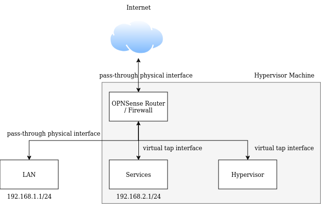
Since the OPNsense is acting as my router, one interface must be the WAN (i.e. your ISP). Typically all other interfaces have the LAN assignment, although for more complex setups you could have VLAN, LAGG, TUN etc. interfaces. Your ISP determines the WAN interface’s IP address, so check with them if they assign it statically, dynamically with DHCP or through PPPoE. The interface which will connect our firewall/router VM to the rest of the home network has a static IP address since we want that to stay constant. OPNSense will also automatically configure a DHCP server for all the other LAN interfaces, so that devices connected to these interfaces can automatically get an IP address. The OPNSense LAN interface also acts as the default gateway for any device connected to the LAN network. Below, is my network diagram of how I plan to segment my network.
Initial firewall rules for interfaces
By default OPNSense blocks all traffic on all of its interfaces. Typically we want to allow devices on these interfaces to access the network and hence must create a firewall rule for it. The rule allows all IPv4/IPv6 incoming traffic from devices on the interface’s network (OPNSense automatically creates an alias “<interface> net” as a shorthand) to reach any destination host and any port.
Secondly, there is little use of having separate interfaces if devices on separate interfaces can reach each other. In my setup, I would prefer if hosts on my services network were not able to access hosts on my home devices network.
Input chain
This chain deals with packets whose target is the router itself. It is vital this is secured correctly
- Accept only established, realted and untracked connections
- Drop all other packets from any address using any protocol on any port (the rule itself should drop all packets, but placing the rule after the previous one means “all other packets”)
Forward chain
- Accept TCP connections to 80, 443, 8080, 53 from LAN devices going out on WAN interface
- Accept UDP connection on 53 from LAN devices going out on WAN interface
- Accept ICMP connections originating from LAN devices (this allows us to ping external services)
- Reject all other packets from being forwarded
DNS over TLS server
Domain name resolution (DNS) is the protocol which converts human readable URLs into IP addresses in order to locate servers across the world. DNS requests are resolved by a server running a DNS resolver software listening to requests on port 53 (default). Typically, you ISP or country runs its own DNS resolver and is where your requests are resolved. However, this is a privacy issue for internet users since whoever is in control of the DNS server can build a profile of the websites you visit. Furthermore, the DNS protocol is an unencrypted protocol. Even if you send DNS requests to a DNS server you trust, anyone sitting between you and the DNS server can simply read the requests you are making.
The choice of a DNS resolver is an important security choice as much as it is a privacy one. A compromised DNS server may direct users to fake IP addresses constituting “man-in-the-middle” attacks. Furthermore, certain DNS servers offer user features such as ad blocking and adult content filtering by not providing IP addresses to requests by you or by websites on your behalf. There are some techniques to secure your DNS requests. A recommended DNS setup will include the following:
- Self-hosted DNS server which supports encrypting DNS requests with TLS
- Trusted upstream DNS server (e.g. Quad9)
The first is to self-host your own DNS server which you can control and trust. OPNSense comes bundled with UnboundDNS which, like dnsmasq, is a DNS server which will run on your OPNSense instance. Running your own DNS server takes care of preventing your ISP/country’s creating a profile. However, the top level domains can still log requests coming from your IP address. Hence, simply running your own DNS server is not enough.
We will begin by creating enabling the UnboundDNS service on OPNSense located in the Services tab. After enabling, the “DNS over TLS” option will become avaialable and where you can enable DoT. On this screen, under custom forwarding, you can also specify upstream DNS servers. Here add the Quad9 DNS IP addresses and leave the domain blank so that Quad9 resolves all DNS requests by default.
Ensuring all DNS requests go over the DNS server
Although, you may be running your own DNS server. Devices on your network can still choose to use a different one. If you do not want to change the DNS settings for all your devices, you can instead enforce all traffic to use your DNS server. With OPNSense, this means creating a port forwarding rule, which forwards all traffic going to port 53 with a destination not belonging to the same source address, and redirecting them to port 53 on 127.0.0.1 (i.e. localhost [the OPNSense router itself]). Test the correct servers are resolving your DNS records with the following website: https://www.dnsleaktest.com/.
DNS resolution for static IP addresses
OPNSense could not resolve hostnames for VMs which had static IP address configured. At first the problem seemed to lie with the my UnboundDNS server, however this was not the case. It is the DHCP server which propagates information such as hostnames and IP addresses to the DNS server. And on closer inspection, the DHCP server did not show any lease information for my static IP VMs specifically. Typically, we configure a machine to use a static IP address on the machine itself. This means the machine sends no DHCP requests to the DHCP server on the router, and hence no hostname information is propogated to the DNS server.
To properly setup static IP addresses on a particular interface.
- Enable the DHCP server on that interface
- Configure the allowable IP addresses on the DHCP server. Ensure your static IP ranges fall outside of this range
- Create DHCP static mappings for the interface.
Selective routing (split tunneling) to external Wireguard VPN
Virtual Private Networks have become quiet popular for home network security. Despite their aggressive advertisements and lofty promises external VPNs simply you:
- Mask your IP addresses from outside servers
- Transfer trust of who gets to monitor your network traffic from your ISP to an external 3rd party. It is important to consider VPN providers can still monitor, sell or leak your network data.
- Added layer of encryption when transferring data between yourself and VPN server
One of the immediate selling points for running your own router VM, is the ability to share a single VPN license across multiple home devices through selective routing. There are number of tutorials on how to do this. I am specifically using the Wireguard implementation of a VPN service. In summary the steps are:
- Set up account with VPN provider
- Set up a Wireguard interface and generate your own public/private key pair
- Ensure the instance is configured with “disabled routes.” Routing decisions will be made via a Wireguard Gateway which we will create later. The gateway IP address can be whatever we choose. It is recommended one number below the IP address provided to us by the VPN provider to avoid conflicts
- Provide your VPN your public key. Your private key remains private
- Your VPN provider will provide an IP address belonging to you on their network
- Create Wireguard peer with the details on one of the VPN provider’s servers (e.g. South Africa). You will need the external VPN’s server public key and IP address of the server
- Create a firewall alias with all the IP addresses of the selected hosts on your network for which you would like to route the traffic through
- Create a gateway for our Wireguard connections. IP address must match the gateway IP address we chose in step 3. The gateway is a far gateway.
- Create a firewall rule to allow selected hosts (i.e. use alias as source address) to still be able to access local network (destination address) for any port
- Create a floating firewall rule to allow traffic out from our IP address as provided by the VPN provider to all devices connected to our Wireguard instance through the gateway we created
- My network is primarily IPv4 at the moment. This means all devices connected to my Wireguard instance will have a private IP address. In IPv4 a private IP address must be NAT-ed to the IP address provided by the VPN provider
Assigning a public domain name and Dynamic DNS (DDNS)
At this point we should begin to think about how to securely expose services hosted on our server such that they can be accessed remotely. Before tackling this we must consider how your connection with your ISP works using IPv4 (the version of the IP protocol still widely used today). We have already run out of available IPv4 addresses. To overcome this, engineers implemented Network Address Translation (NAT). NAT introduced private and public IP addresses. In this setup, all your local devices with have a private IP address managed by you. An ISP will then provide you with a single IP address. The source address for all traffic exiting the home network router will be substituted with the ISP’s public address and when receiving data the destination address is swapped back to the private address. A home network’s private IP address space is independent of their neighbors. Thus the two homes can freely use private IP addresses, allowing us to save IP some addresses.
Although this worked for a while, the still ever growing number of internet devices meant ISPs had to apply this tactic a second time. Carrier Grade NAT (CGNAT) means instead of your ISP assigning you a single public IP address, they instead assign you a private address on their network (typically 100/). Thus traffic leaving and entering your network must be NAT-ed twice. CGNAT is also referred to as double NAT.
It is difficult to host services behind CGNAT, since the only IP address assigned to you is a private address only known to your ISP. Devices an external networks will not be able to reach it. To overcome this it is possible to request a public IP address from your ISP so that devices on an external network can reach you. If your ISP cannot provide you with a public IP address, you may look into hosting your services with an IPv6 service (the are exponentially more IP addresses with IPv6 and hence NAT is not necessary) or establishing a VPN tunnel from within your network by connecting to a Virtual Private Server (VPS) or Cloudflare’s Argo tunnel. Once a connection is established, the VPN server can route traffic to you.
The public IP address your ISP provides to you can be either static or dynamic (obtained through DHCP). Static IP addresses are ideal for hosting service, however, ISPs charge extra for the privilege. I had to settle on a dynamic public IP. Given, I don’t know when my IP address would change, I bought a domain name which would stay constant for all my users and service configurations. I then setup a Dynamic DNS (DDNS) software tool which runs on OPNsense and continuously pokes a DDNS provider informing them from which IP address you are connecting from. This DDNS provider would then continuously update their DNS records so remote devices will always have the latest IP address assigned to my domain name.
Remote access through Wireguard VPN
It will be useful, if the services we begin setting up in the next section, were also available remotely (i.e. we could connect to them from outside our home network) without exposing the services directly to the internet through the router. This is precisely the main use-case of a VPN. Only authenticated users will have access to the services and data transmitted is highly encrypted.
- Create Wireguard server instance. This includes setting the tunnel address (which is also the address for the DNS server)
- Create Wireguard peer instance
- Assign interface to Wireguard server instance
- Add rule to WAN interface to allow incoming UDP traffic from any source address going to WAN address on port 51820. This rule allows our external clients to connect to the VPN server through the internet
- Add rule to Wireguard interface to allow traffic from any Wireguard client (i.e. any source) and protocol to access selected IP ranges
- Remember to include the DNS server. Same as tunnel address set in step 1.
- Add “shaping” rules…
SSL/TLS certificates
Background
On the internet, it is well known an attacker can intercept traffic to a service such as a banking app and can simply transfer data between the user and banking app. From the user’s perspective they will be unaware their traffic is moving between a “man-in-the-middle.” Such an attack is possible even if the traffic itself is encrypted since the user is encrypting their data with the attacker’s public key and not the true server. Thus web hosted services need to use certificates to prove that they are indeed who they say they are. Only once their identity is proven, can the encryption keys be exchanged.
Trusted certificates belong to a chain of trusted certificate authorities which browsers all know. A certificate to a web service actually forms a chain. There are a handful of certificate authorities which browsers trust. A certificate authority must sign the certificate to prove the service is legit.
When connecting to the OPNsense web UI, the web browser, throws a warning that the certificate is untrusted. In almost all home use cases, you can ignore this warning and continue to the web UI. To remove the warning you have the following options available to you, in order of complexity:
- Add OPNsense self-signed certificate to your browser’s list of trusted certificates
- Create and configure each service to serve a Let’s Encrypt certificate
Installing Let’s Encrypt certificates on individual services
Option 1 may be the easiest if the number of devices connecting to your home services are small since it requires you to add the certificate to a trusted list on every device. Option 2 is a free way to overcome this. Let’s Encrypt is a trusted Certificate Authority on most browsers. In order for Let’s Encrypt to accept your Certificate Signing Request (CSR), you must prove you control your domain. Man-in-the-middle attackers cannot do this. Passing Automatic Certificate Management Environment (ACME) challenges prove you have control over your domain. Of these challenges the recommended on is proving you have control over the DNS records for your domain. Thus the process for obtaining a signed certificate from Let’s Encrypt for a domain managed by Cloudflare is as follows:
- Generate API key on Cloudflare dashboard
- Install os-acme-client plugin on OPNSense instance
- Add account in os-acme-client settings (see under Services tab)
- Create an ACME DNS challenge (see Challenge Types under ACME client). Provide your Cloudflare API key here
- Create certificate. Only provide common name (fully qualified name of your service) and ACME account and challenge type
- Finally issue/renew certificate
As previously mentioned, Let’s Encrypt certificates expire earlier than other paid options. For this reason, the os-acme-client plugin includes some automation features for renewing the certificate. It is important to note however, not all services are capable serving content over HTTPS, yet we still may want to.
Using a reverse proxy for forwarding encrypted data to client
- Create ACME DNS wildcard challenge on Nginx Reverse Proxy Manager
- Override domains on our local UnboundDNS server to point to Nginx Reverse Proxy Manager
- Add reverse proxy hosts which encrypt traffic to user and decrypt and forward data to non-HTTPS service
Setting up Docker services
General
For a VM setup completely specific to me, I decided to put all Docker related data such as the location of the images and volumes onto an external drive instead of the VM’s home directory. To accomplish this I added a “data-root” key into the /etc/docker/daemon.json configuration file.
Did you know that the Docker daemon runs its own DNS server? Annoyingly Docker ignores the host’s systemd-resolved configuration and frustrating when all my services are local and do not have public DNS records associated with them. We can override Docker’s DNS server with the /etc/docker/daemon.json configuration file and restarting the daemon.
{
    "data-root": "/mnt/external_storage_path",
    "dns": "10.0.0.1"
}
sudo systemctl restart docker
Networking
Docker provides us with 3 types of networks, namely:
- Host (or default)
- Bridge
- macvlan
I selected to use macvlan networking, given it has simplicity and lighter overhead (the virtual device does not need to learn IP addresses). The docker network needs to be given the range of IP addresses given to containers assigned to this network (subnet). Secondly we must assign a parent interface through which all external traffic to/from our containers will go (gateway). We will assign the host’s actual ethernet interface as well as give it an IP address so our containers can locate it. Finally, when spinning up our Docker containers, just remember to specify the newly created network and optionally assign it an IP address.
docker network create \
    --driver macvlan  \
    --subnet=192.168.2.0/24 \
    --gateway=192.168.2.1 \
    -o parent=ens1 docker_network

docker network ls # show newly created network

docker run -d container \
    --name=container1 \
    --net=vm_docker_net \
    --ip=192.168.5.2 \
Shared database server with Docker
A lot of services require a database. In my environment, I specifically wanted a single database server running as a Docker container and have my other services (also running as Docker containers) sharing this single database server. This means I avoiding “all-in-one” container solutions which package in their own database servers. First setting up a shared database server container requires some admin work before the rest of the services start. I have outlined the steps specifically for PostgreSQL below.
# 1. Create container
docker run -d \
    --name postgres \
    --net=vm_docker_net \
    --gateway=192.168.0.1 \
    -o parent=ens1 \
    --env PPSTGRES_PASSWORD='secretpassword'
    --volume <path_to_volume_on_host>:/var/lib/postgresql/data \ # Path for PostgreSQL configuration files
    postgres
At this point, you will be able to ping the container and even see an open port 5432 (default for PostgreSQL) if you scanned the host. However, if you tried connecting to the database from another local machine, you would see an authentication error. This is because by default, PostgreSQL does not allow any non-local connections. By modifying the configuration files which we mounted in the previous step, we can adjust this behaviour.
# docker cp <container>:/<path_in_container> <destination_in_host>
docker cp postgres:/var/lib/postgresql/data/pg_hba.conf .
# edit file on host
We are going to allow the follow LAN IP ranges access to the database by adding the following 2 lines to the pg_hba.conf file we copied from our container. And then copying the edited file back to the container in a similar fashion to how we obtained it.
# IPv4 LAN connections
# host  DATABASE        USER            ADDRESS                 METHOD
host    all             all             192.168.1.1/24          trust
phost    all             all             192.168.2.1/24          trust
docker cp pg_hba.conf <container>:/var/lib/postgresql/data
docker restart postgresTest your connection to the database a LAN machine which has the PostgreSQL client tools installed.
psql -h <ip_of_container> -U postgres -d postgresNow that we have LAN access to the database, we can create users and databases for each of services offering a little more security. By default our newly created user will not have access to the default database. Instead the newly created user will have full access to only their newly created database.
CREATE USER nextcloud WITH PASSWORD 'secretpassword';
CREATE DATABASE nextcloud_db;
GRANT ALL PRIVILEGES ON DATABASE nextcloud_db TO nextcloud;
ALTER DATABASE nextcloud_db OWNER TO nextcloud;
Guestfs
My VMs were created with LVM logical volumes which make extending and reducing the size allocated to VMs easier to work with. When a VM is installed, it will create a disk image with a partition table within its LVM volume. This means we can’t simply mount the LVM volume when requiring access to a VM’s filesystem. Instead we must use libguestfs package designed to mount guest VM disk images. Note it should be apparent, that you cannot mount a filesystem with write access whilst the VM is running since the VM will be unaware another operating system may be writing to the disk.
Tour of guestfs
virt-filesystems --long -h --all # list all partitions on guest

virt-resize --resize  # resize partitions for guest

virt-copy-in -d <guest> <file_to_be_copied_in> <destination_in_guest>
References
https://letsencrypt.org/how-it-works/ Writing udev rules Udev (Arch Wiki)